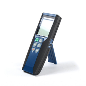
Overview
HETMCTDL-131 is featured with outstanding performance and easy operating function along with high visibility colour LCD display, universal inputs with high speed of sampling rate and accuracy. Measured data is stored into memory and can be analyzed on PC trough communication.
Features
Basic Functions
- Up to 48 channels of universal input
- UP to 18 Alarm Output Relays
- With 24V Power distribution Output
- Communication type: RS485, RS232C.
- With a USB data transfer interface
Display & Operation
- Multiple display Function: Choose the display your way
- Use date and time calendar search functions to Review historical data.
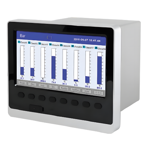
- 7 inch high brightness colour graphics and colour LCD (800 * 480pixels)
Reliability and Security
- Dust and splash-proof front panel
- Power Fail Safeguard: All the data stored in flash memory, make sure that all the historical data and configuration parameters will not lost when power fail. Real time clock power supply by lithium batteries.
Data Acquisition Software
Software for varieties of tasks: analysis, settings, and acquisition.
Power Supply
Voltage range: AC 85 ~ 264 V (power supply of the switches), 50/60 Hz;
DC12 ~ 36 V (power supply of the switches);
Normal operating condition
- Temperature: 10 ~ 50℃
- Humidity : 10 ~ 90%%RH(without condensation of moisture)
Technical Specifications:
| Input Measurement | |
| Input signal | Current: 0 ~ 20 mA, 0 ~ 10 mA, 4 ~ 20 mA, 0 ~ 10 mA SQRT, 4 ~ 20 Ma SQRT Voltage: 0 ~ 5 V, 1 ~ 5 V, 0 ~ 10 V, ±5 V, 0 ~ 5 V SQRT, 1 ~ 5 V SQRT, 0 ~ 20 mV, 0 ~ 100 mV, ±20 mV, ±100 mV
Thermal resistance: Pt100, Cu50, Cu53, Cu100, BA1, BA2 Linear resistance: 0 ~ 400 Ω Thermocouple: B, S, K, E, T, J, R, N, F2, Wre3-25, Wre5-26 |
| Output | |
| Output signal | Analog output:
4 ~ 20 mA (load resistance ≤380 Ω), 0 ~ 20 mA (load resistance ≤380 Ω), 0 ~ 10 mA (load resistance ≤760 Ω), 1 ~ 5 V (load resistance ≥250 KΩ), 0 ~ 5 V (load resistance ≥250 KΩ), 0 ~ 10 V (load resistance ≥10 KΩ) |
| Alarm output: normally open relay contact output, where the contact capacity is 1 A/250 VAC (resistive load)
(! Note: Please do not carry load directly in case the load exceeds the contact capacity of relay.) |
|
| Feed output: DC24 V ± 1, load current ≤250 mA | |
| Communication output: RS485/RS232 communication interface, 1,200 ~ 57,600 bps baud rate (able to be set); standard MODBUS RTU communication protocol is adopted; the communication distance of RS-485 can be as long as 1 kilometre; the communication distance of RS-232 can be as long as 15 m; Ether Net communication interface is adopted, where the communication speed is 10 M. | |
| Comprehensive parameters | |
| Measurement accuracy | 0.2% FS ± 1d |
| Sampling period | 1 s |
| Setting mode | The button is set in the form of panel soft touch; set values of parameters are locked with passwords and will be saved permanently in case of outage. |
| Display method | 7-inch 800×480 dot-matrix widescreen TFT high brightness color graphics and LCD display; LED backlight; with clear pictures and wide visual angle.
Display contents can be composed of characters, figures, conditional curves, bar graphs, etc.; through panel button, page turning, forward and backward search of historical data, time scale change of curves, etc. can be realized. |
| Data backup | Data backup and conversion storage of USB flash disk and SD card are support, where the maximum capacity is 8 GB; FAT and FAT32 formats are supported. |
| Storage capacity | The capacity of the internal Flash memory is 64 M Byte. |
| Recording interval | Nine options including 1, 2, 4, 6, 15, 30, 60, 120 and 240 s can be selected. |
| Storage Function | |
| Data backup | Data backup and conversion storage of USB flash disk and SD card are support, where the maximum capacity is 8 GB; FAT and FAT32 formats are supported. |
| Storage capacity | The capacity of the internal Flash memory is 64 M Byte. |
| Recording interval | Nine options including 1, 2, 4, 6, 15, 30, 60, 120 and 240 s can be selected. |
| Storage length (continuous record without power-off) | 24 days (1 s interval) – 5825 days (240 s interval)
Calculation formula: recorded time (day) (! Note: For calculation of channel number, the program divides the channel number into five options, namely 4, 8, 16, 32 and 64, and the bigger figure should be regarded as the channel number for calculation in case the channel number of the instrument is between the said two options. For example: If the channel number of the instrument is 12, then 16 should be adopted in the formula.) |
| Alarm Output Function | Max 18 channel alarm output, normally open relay contact output, where the contact capacity is 1 A/250 VAC (resistive load)
(! Note: Please do not carry load directly in case the load exceeds the contact capacity of relay.) |
| Communication Function | RS485/RS232 communication interface, 1,200 ~ 57,600 bps baud rate (able to be set); standard MODBUS RTU communication protocol is adopted. |